Code to use the Raspberry Pi as a two RF swith controller for running Reconfigurable antenna experiments on the grid through DYSE. The tested OS for the raspberry Pi was 2019-04-08-raspbian-stretch-lite but any lite version will work.
This code can be used without having to physically ssh into the Raspberry pi, an example of this would be the following code (sends socket command to socket port PORT and code CODE to that port):
sshpass -p ********* ssh -oStrictHostKeyChecking=no -X pi@raspberrypi-dyse "python /home/pi/dyse-rfswitch-controller/python/client_cli.py localhost *PORT* *CODE*" > /dev/null 2>&1 &
The following would toggle automatically the states of the antenna, could be use concurrently with dragon radio or integrated within the code itself:
  """ This code randomly selects the RALA state"""
  import os
  import random
  from time import sleep

  rpi = "raspberrypi-dyse"
  interval = 0.5 # Amount of seconds to sleep

  myCmd = './rpi_control.sh --rpi '+rpi+' --port 8081 --mode 1' # Select RALA on the RFSwitch
  os.system(myCmd)

  # Randomly change state for RALA (0 - omni, 1-4 directional)
  while True:
      mode = random.randint(0,4) # Random between 0 and 4 both included

      # Send the command
      myCmd = './rpi_control.sh --rpi '+rpi+' --port 8080 --mode '+str(mode)
      os.system(myCmd)

      # Wait interval amount of seconds
      sleep(interval)
sp4t_control.cc: This file is the controller of the SP4T switches.
To compile it, run the following (wiringPi needs to be installed):
g++ sp4t_control.cc -o sp4t_control -l wiringPi
The controller should be set up to run on boot, so that it is always ready (intructions at the end). If you want to check from the terminal whether the controller is running or not run: ps aux | grep "sp4t". If the controller is running but the switches don't seem to work, double chech the connections.
The Raspberry Pi is listening on port 8081 for a socket connection. A python example shows how this connection could be achieved in order to send the desired state for the rfswitches.
client_cli.py: it can be used aspython3 client_cli.py pihostname 808X state. If run locally within the pi use localhost, if used from the grid use the hostname of the raspberry.
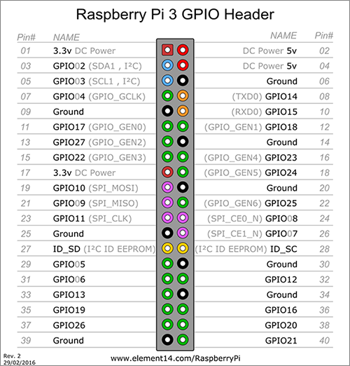
Unless the user changes the pins on the code, the SP4T has to be connected to the Raspberry Pi 3 Model B as follows:
| SP4T1 | Raspberry Pi |
|---|---|
| A | GPIO17 |
| B | GPIO27 |
| Vcc | 3V3 |
| GND | GND |
| SP4T2 | Raspberry Pi |
|---|---|
| A | GPIO23 |
| B | GPIO24 |
| Vcc | 3V3 |
| GND | GND |
It is important to note that the RFswitch will always have a mode enabled (as 0,0 enables port 1). If some of the rfswitch ports are unused, we will have to put a cap at the end of the connector to avoid interfering over the air.
-
Clone the repository on ~/ == /home/pi
cd git clone git@github.com:drexelwireless/dyse-rfswitch-controller.git -
Set a cron job to start the controller on startup
% Make sure the startup script can be executed chmod +x /home/pi/dyse-rfswitch-controller/startup.sh crontab -e % Add the following to the crontab list @reboot /home/pi/dyse-rfswitch-controller/startup.sh -
Compile the cpp code:
cd ~/dyse-rfswitch-controller/cpp g++ sp4t_control.cc -o sp4t_control -l wiringPi -
Change the hostname of the pi, so that you can ssh in it. Also enable SHH
sudo raspi-config # Change the keyboard and locale too -
Reboot the system and test everything works
sudo shutdown -r -
Check the controllers are running:
ps aux | grep "sp4t" # Should see both controllers -
Connect all the hardware and use some LEDs to see what state is being selected (this way you test your connections are correct visually, trust me, it will save you some headeaches). For this use the python
client_clito manually toggle the modes.
Some errors may occur, the most common ones are:
- Depending on how Raspbian is installed, wiringPi might not be available by default and it need to be installed.
- Make sure the hostname is consistent.
- Add graph of hardware connections and LED setup for visually debugging

