-
Notifications
You must be signed in to change notification settings - Fork 5
BuildEMProbe
- Copper wire for EM pickup coil (Diameter 0.15 mm)
- Helper copper wire (Diameter 0.5 mm, depends on desired coil diameter)
- Amplifier PCB + components
- Steel injection needle
- Super glue
- Solder
- Solder paste
- Insulation tape
- Soldering iron
- Hot-air soldering gun (optional)
- Two tongs
- Wire cutters
- Dremel tool (or different tool for cutting the steel frame)
- 5 V DC power supply (can be wall-plug type)
- Multimeter (for testing power supply)
Connect the PCB to 5 V DC. The red LED should turn on.
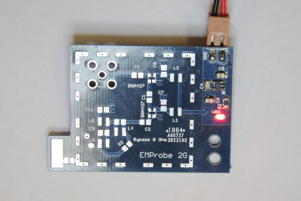
Note: Do not install the power connector on the component side. Also, we strongly advise to use a polarized connector as the circuit does not have protection against accidentally swapped VCC and ground lines.
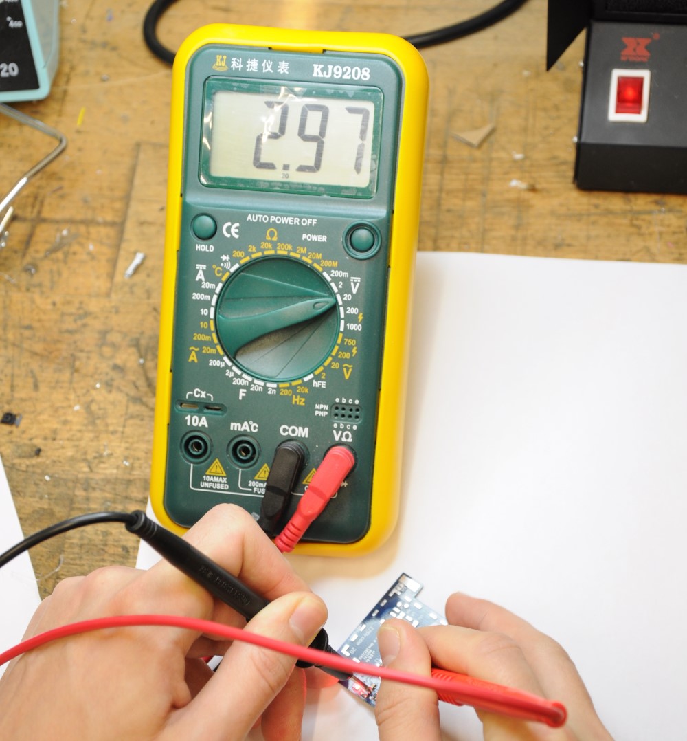
Measure the regulated voltage (e.g. at the left end of L1 in the upper picture) vs. ground, should be very close to 3 V:
(do not forget to clean it, this was not done in the pictures here :)). Make sure the SMA connector is on the non-component side of the PCB. Also make sure that the pins of the SMA connector are short enough and do not reach the height of the PCB shielding (to be installed in the final step):
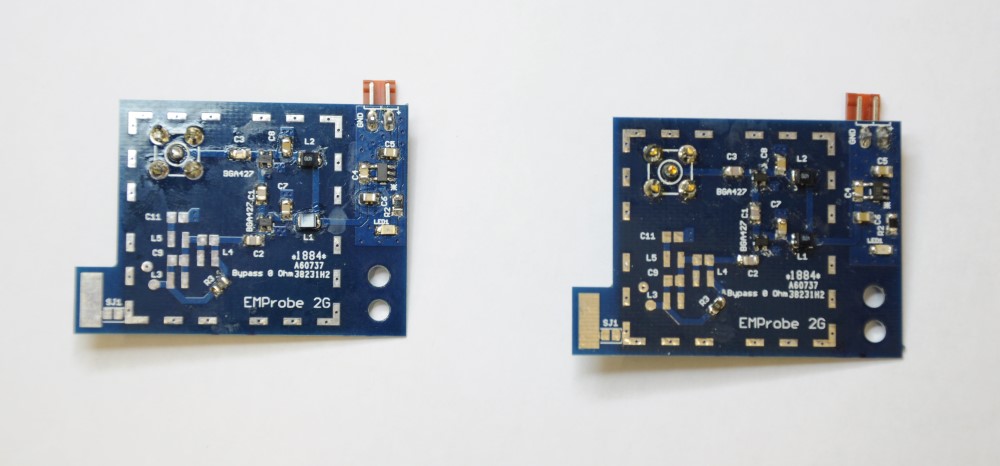
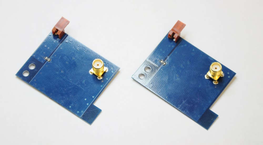
Note: The input filter is not mounted here and bypassed via a 0 Ohm resistor on pad R3. Also, do not forget to install the 0 Ohm resistor connecting the two ground planes on the non-component side.
The next steps are to prepare the actual coil picking up EM emanations:
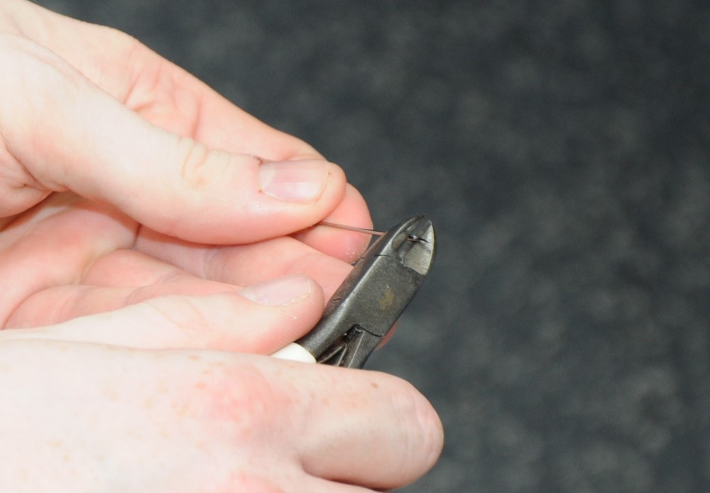
Cut a hollow steel injection needle to the desired length (approximately in half). Be careful with the sharp remaining parts.
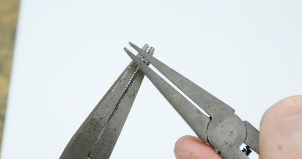
To re-open the end of the needle (where it was cut), use two tongs. Be careful to not permanently destroy the needle (can happen easily):
Here, we used five turns of 0.15 mm copper wire, wound around a thicker copper helper wire (TODO: which diameter?). First, fix the coil wire using insulation tape orthogonal to the helper wire.
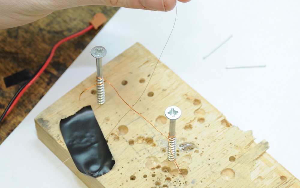
Now, wind the wire five times around the helper wire, leave a space of approx. 1 mm between each winding:
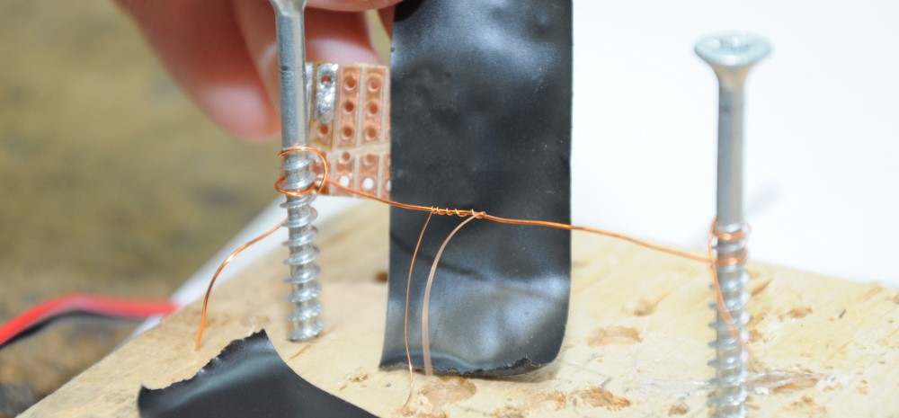
Then, push the windings together – best use your fingers to not damage the thin coil wire. You end up with a small coil like this:
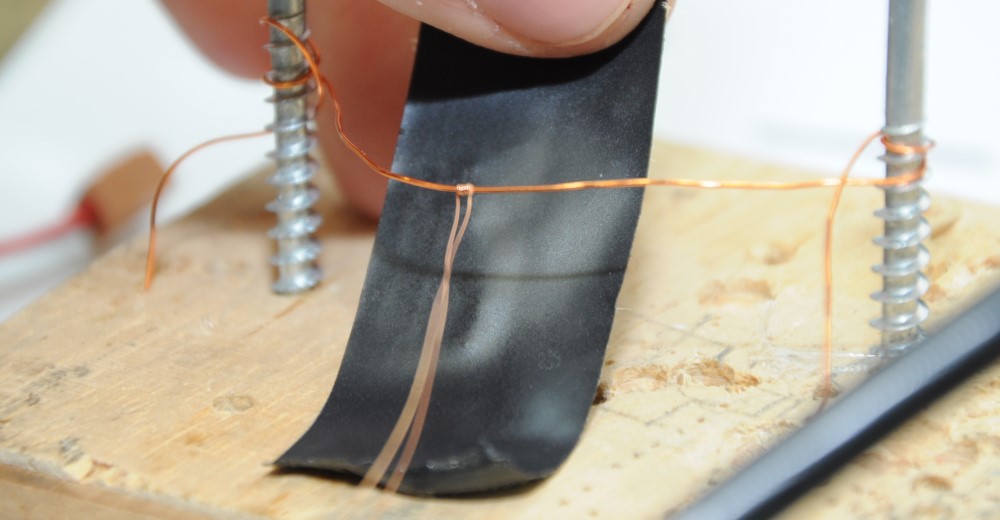
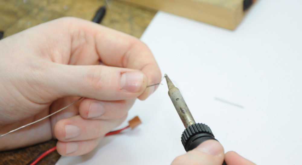
Twist the open wire ends a few times at one end of the coil (twisting them in the middle will make it harder to correctly align the coil later). Push the wires through the hollow guide prepared before. Then, cut the wire ends to approx. the length of the metal guide plus 1 – 2 cm. Solder-coat both ends:
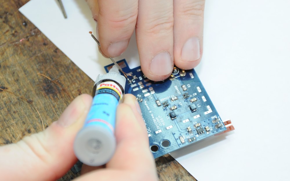
Make sure that a (short piece) of the metal guide is within the shielded area. Shorten the probe wire ends as necessary and solder them to the input connection points on the PCB. The probe should be installed at approx. 45° with respect to the middle axis of the PCB. The actual coil should again be parallel tot he PCB edge to be able to put the probe flat on top of a chip later. Use super glue to fix the probe guide on the PCB (soldering on the large pad is near-impossible if a steel needle is used):
The result should look like this:
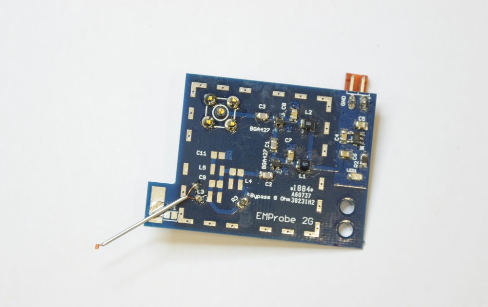
Once the coil is in the correct position, you may fix it using a drop of super glue. This makes it mechanically more stable.
The metal shield reduces the noise floor of the amplifier a bit (tests show about 5 - 10 mV reduction of peak noise amplitude) and helps to mitigate external influences (e.g. GSM/UMTS/LTE signals). Nevertheless, due to the small dimensions of the probe, it is quite a good antenna for cellphone/Wifi/... frequencies etc., so keep such devices away while measuring.
First, part of the shielding frame (in the lower-left corner) has to be removed to make space for the probe guide. In the below example, this part is actually a bit large, you might take away a smaller piece. We used a dremel tool, be careful with steel parts flying around...
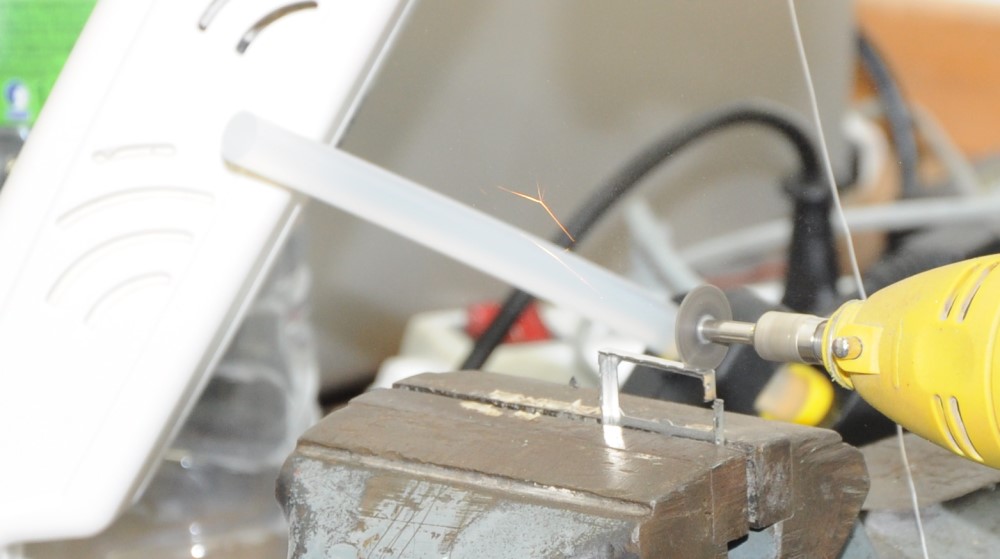
To install the shielding, we put solder paste on the respective pads on the PCB, placed the frame, and heated each pad with a soldering iron (not hot air):
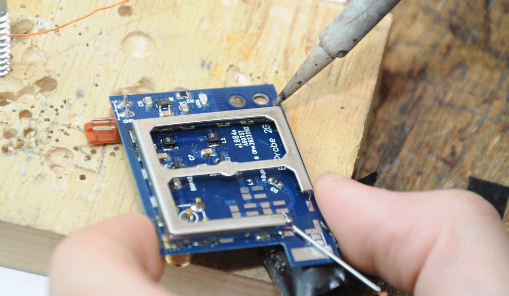
Using a hot-air gun as a final step to remove solder paste that was not properly heated is sometimes helpful especially for the inside of the frame. Finally, put the shielding cap on the frame (which might have bent a little) and have fun with your newly built EM probe.
Final very important reminder: Only use high-precision measurement instruments like the KJ9208 multimeter we had :):
