-
Notifications
You must be signed in to change notification settings - Fork 8
HW Turnout actuator
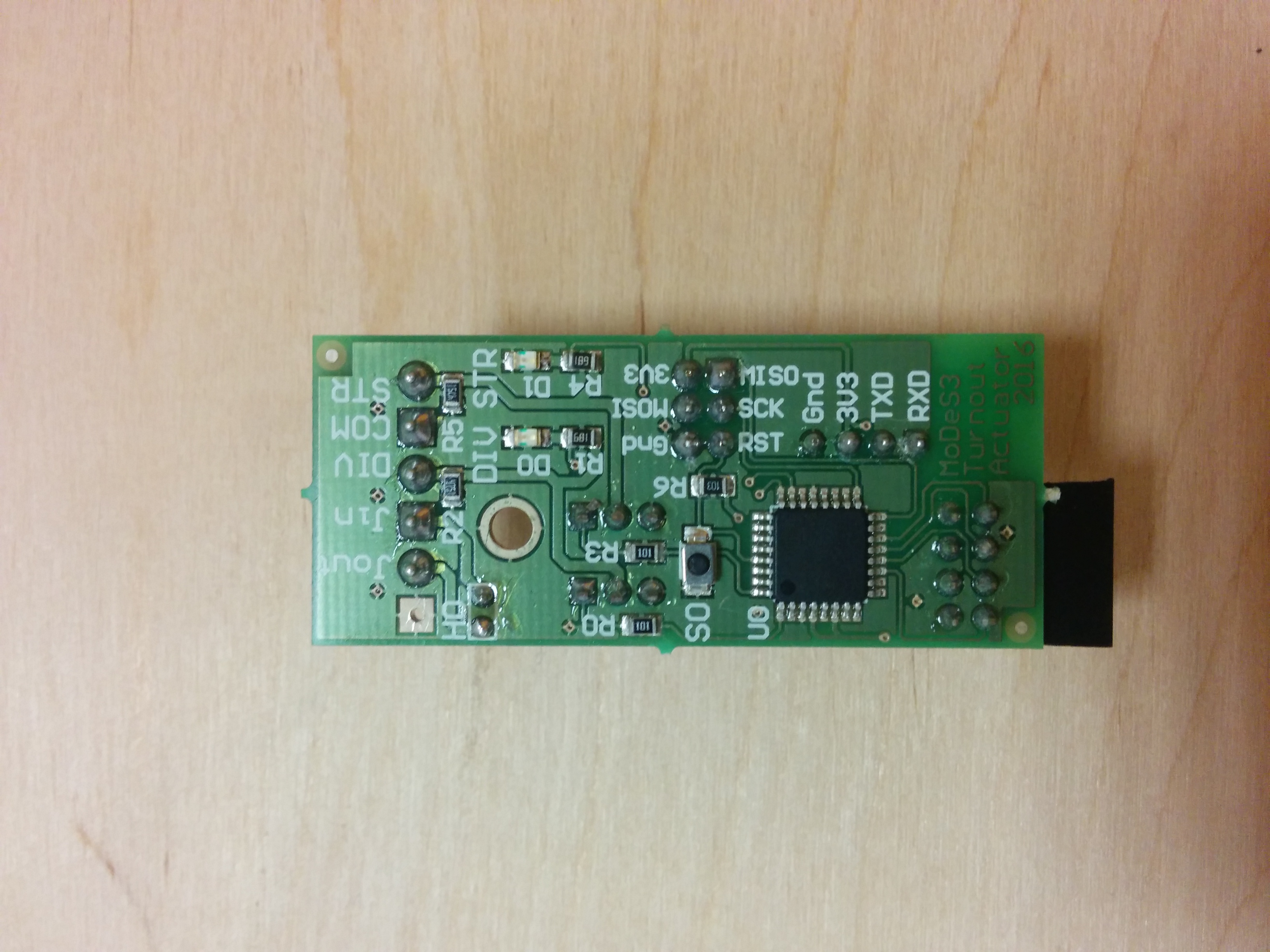
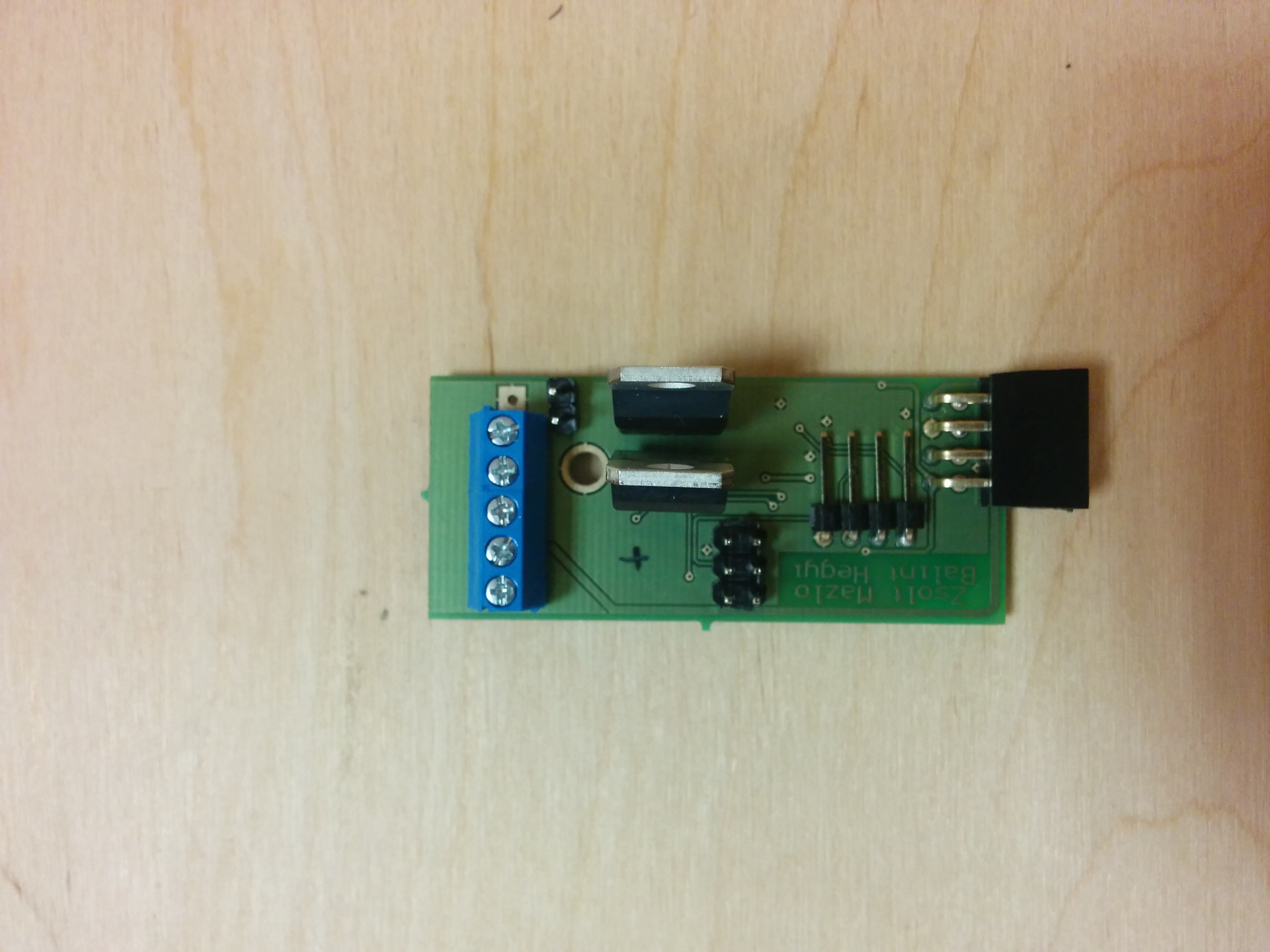
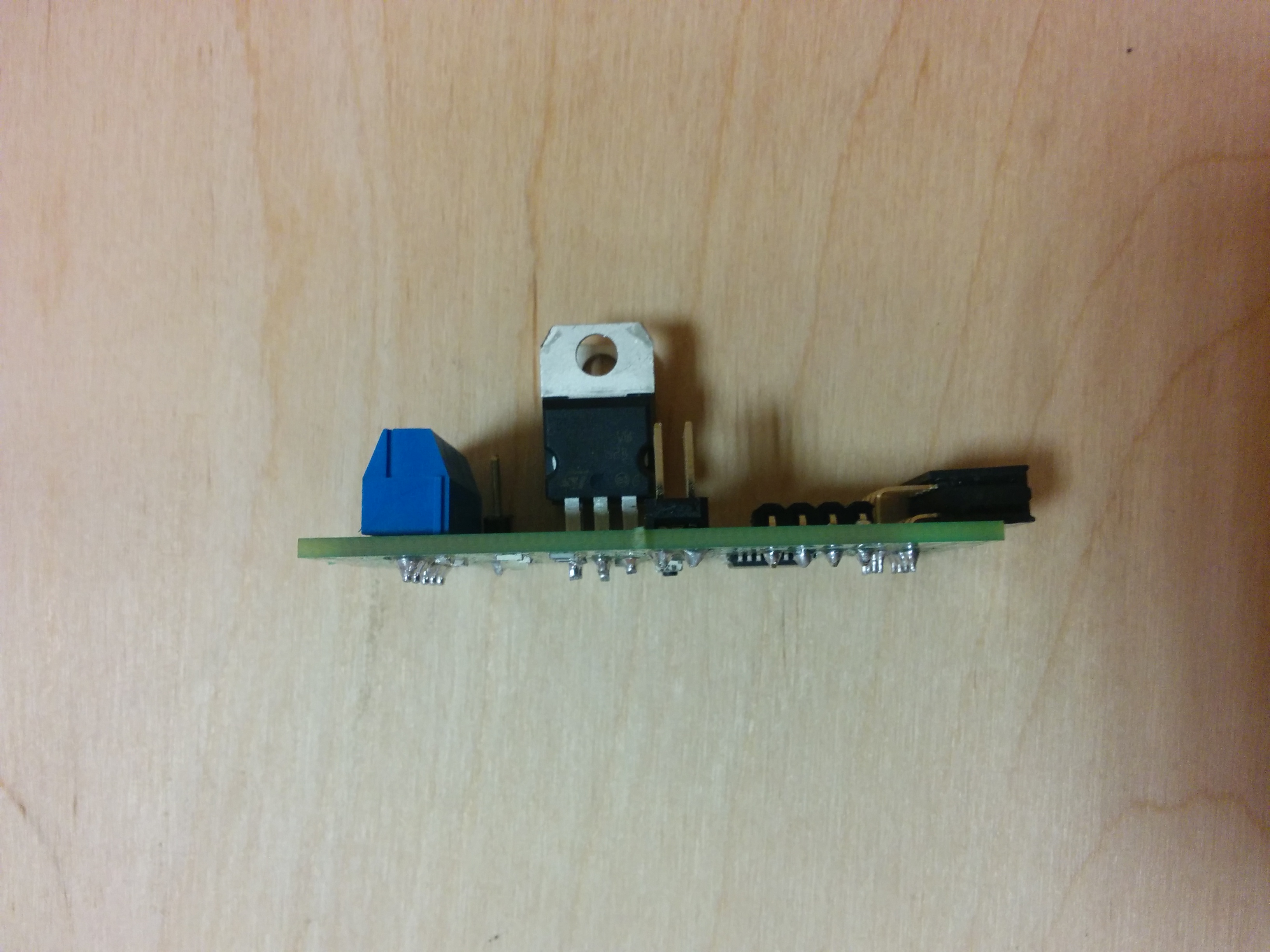
Turnout Actuator expanders can switch turnouts on the table. Previously, we have managed to solve this with COTS units, but in that case we weren’t able to query the position of the switch programmatically. This expander gives the ability for both switching the turnout and sensing its state.
The concept behind this unit is based on the fact, that turnout mechanism is working as an wire between the common (COM) pole and an other pole (STR or DIV) when switched in one position, therefore we can sense its state.
The electronic characteristics of the BeagleBone unit couldn’t satisfy the switching process electrically, thus we had to use a microcontroller (an Atmega328 MCU). Also, the state-sensing process is based on Analog to Digital Converters, which are also integrated into the MCU.
The MCU has 2 inputs and 2 outputs connected to the expander connector as shown in the table below (front view).
| pin0 | pin1 | pin2 | pin3 |
|---|---|---|---|
Turnout switching to Straight position |
Turnout switching to Divergent position |
Turnout state sensing (Straight) |
Turnout state sensing (Divergent) |
INPUT for the MCU |
INPUT for the MCU |
OUTPUT for the MCU |
OUTPUT for the MCU |
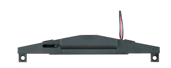
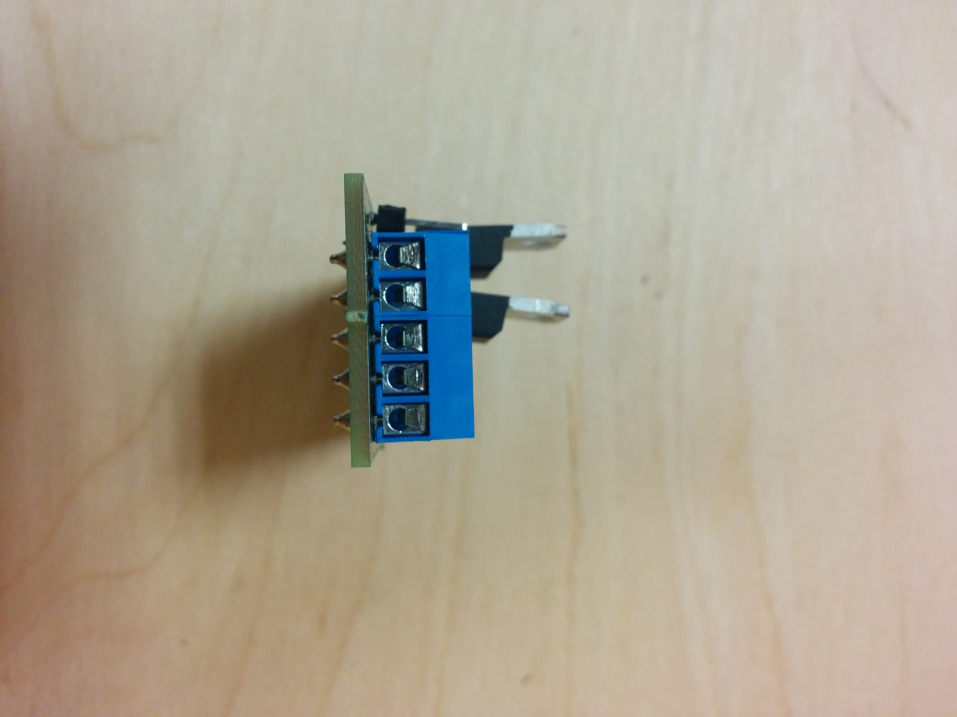
The Turnout Actuator expander has a 5 pole terminal-block for wiring, and it is tested only with PIKO 55271 turnout mechanism so far (link::http://www.vasutmodell-centrum.hu/palyaepites/sinrendszerek/piko-55271-elektromos-allitomu-balos-jobbos-h0-p-19536-73-3.html?utm_source=termek-kartya&utm_medium=termek_kep&utm_term=termek-Piko%2055271&utm_campaign=termekkartyarol-adatlapra[PIKO 55271 item in an hungarian webshop]). The turnout mechanism should be connected to the DIV, COM, and STR poles directly, red wire goes to COM pole and the two black wires to the DIV and STR poles. Unfortunately, there is no way to distinguish which black wire goes in which pole, therefore to use the turnout mechanism correctly, the controller software must be calibrated after wiring after wiring.
Also, there are two other poles for connecting the turnout rail to the occupancy sensor, which are routed to a jumper connector — this jumper connector could be used for any other purpose later, for now the two wires are connected directly.
All Turnout Actuator expanders are already flashed with the right firmware version, but the board has the ability of uploading new firmware to the MCU. Currently, we are using the Arduino bootloader and Arduino-based code for this purpose, but there is an option to use AVR-C or even assembly.
To upload a new firmware, there are two options:
-
There is a dedicated In-system programming (ISP) interface on the board,
-
and there is a UART interface for uploading Arduino-based codes.
Caution: For uploading Arduino-based codes, the chip should be flashed with the Arduino bootloader before.
Caution: To upload new Arduino bootloader to the board, the FUSE bits must be set to use internal oscillator instead of external oscillator.
Hint: Do not try to upload new Arduino bootloader, it is hard to bring back to life an MCU if you do something wrong :) With uploading Arduino-based codes, it is much harder to mess things up.
